“That’s clearly left !”
3D hearing is a learned skill where your brain deducts the direction that a sound is coming from based on clues such as:
- inter-ear timing differences Which ear does it reach first?
- inter-ear volume differences Is it louder on the left ear?
- frequency envelopes Is the signal lacking high frequencies?
- reflections Was the signal reflected by your ear shell?
![]()
As such, the spatial localization of a given sound is a guess that your brain makes based on measurable signal attributes. With my Hajo’s headphone enhancer product, I try to go the exact opposite direction. By simulating timing, volume, frequency envelope and reflections, I can trick your brain into believing me that the sound is coming from a desired direction.
In other words, I can make it possible to hear 5.1 surround sound (or even full 3D) over regular headphones by exploiting that psychological trick. This article will try to explain how that works in more detail. It is divided into 3 parts:
- Coding, which explains the software engineering tasks to make real-time audio modification possible and convenient
- Mathematics, where I try to explain the basics of FIR filtering
- Acoustics, where I show how I design FIR filters for surround sound simulation on headphones with bass boost.
Coding
This part will explain the coding work required to clone my Hajo’s headphone enhancer product. As such, it might be helpful for you to download my trial (which, BTW, never fully expires) to follow along and inspect the components.
Modify the OS X audio stream in real-time
While I know that there’s an internal DSP Manager embedded into apple’s HDA driver, this is not exposed publically and since it seems to be used internally to compensate for differences in hardware, I’m not sure if it would be safe to use in a product.
As such, the only way to access the OS X audio stream in real-time is to provide your own sound card kernel driver. Luckily, this is a lot easier in practise then it sounds :)
First, you subclass IOAudioDevice and in it’s initHardware function create an instance of your own subclass of IOAudioEngine. The IOAudioEngine will then create (and add to itself) objects for the audio streams (1x input, 1x output, type IOAudioStream) and allocate temporary buffers.
In clipOutputSamples, you now copy the output samples that OS X wants to play through your sound card into your temporary buffer and in convertInputSamples, you copy the temporary buffer into a sample buffer that your app can access through the OS X audio system.
ioreg is your friend
If you’re following around, you might now want to install my app and use the ioreg command line tool or the IO Registry Explorer app to take a look. You should find a HajoHeadphoneEnhancerDevice which owns a HajoHeadphoneEnhancerEngine which owns two audio streams. The HajoAudioStream is the output stream (= where OS X will send the music) and the regular IOAudioStream is the input stream (= where your app will read the data from).
So basically, your fake sound card driver will just echo back any output that OS X tries to play as a fake input audio stream. That means your app can now change the default output device to your fake sound card and then stream from your fake input stream to the regular OS X sound card output.
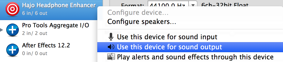
If you’re following around, you can easily check this by using the Audio MIDI Setup utility app to set my “Hajo Headphone Enhancer” sound card as the default output device and start playing some music. Now, you should be able to record the music that is playing by capturing the input stream of the “Hajo Headphone Enhancer” driver using a regular recording tool such as Audacity.
Signal flow
Sound-playing apps –> OS X –> Kernel mixer –> Output stream of fake sound card –> Input stream of fake sound card –> OS X –> Your app –> OS X –> Output stream of real sound card
There’s an Apple example called “Audio Reflector Driver” that will help you get started with the fake sound card driver required to make this work. Inside your app, you just use AudioDeviceAddIOProc and AudioDeviceStart for both the input and the output stream to register callbacks which can then communicate with each other through a ring buffer.
Making the volume change hardware keys work
Apple’s built-in volume bezel uses kAudioHardwareServiceDeviceProperty_VirtualMasterVolume, kAudioDevicePropertyVolumeScalar and kAudioDevicePropertyMute. So to make the bezel work nicely with your fake sound card set as the default output device, you’ll need to instantiate volume and mute controls and add them to the output stream of your fake sound card. To do so, just use IOAudioLevelControl::createVolumeControl (-144 to +12 dB), IOAudioToggleControl::createMuteControl and addDefaultAudioControl, which are all provided by IOAudioEngine.
You don’t need to actually do anything inside the driver when the control change callbacks fire.. since your app will handle all that for you. Use AudioDeviceAddPropertyListener and AudioHardwareServiceAddPropertyListener inside the app to mirror the volume and mute status of your fake sound card over to Apple’s built-in sound card. That way, your app doesn’t have to bother modifying the audio signal, because the official sound card driver will do it for you :)
Getting access to 5.1 surround data
If you’re following along, now would be a good time to try out my app with a 5.1 video, such as this one: https://www.youtube.com/watch?v=juIJGBxj-4w
I hope you’ll agree that my app really does play back the full 5.1 signal, as opposed to the stereo mixdown one would regularly expect on headphones.

To make this work, your fake sound card driver needs to a speaker layout configuration to interested apps, so that Chrome or VLC know which channel ouf your output stream is supposed to be which speaker. BTW, these are the same channel assignments that you can modify with the “Configure Speakers…” button in the Audio MIDI Setup utility for real-world surround sound cards.
Internally, apps will query your driver’s user client for the kAudioDevicePropertyPreferredChannelLayout property. So you need to implement a HAL plugin which returns the speaker layout that you’d like to capture. The magical functions to override are AudioDriverPlugInDeviceGetPropertyInfo and AudioDriverPlugInDeviceGetProperty. In my implementation, I just use IORegistryEntryCreateCFProperty to store the required data inside the ioreg tree.
If you’re following along, take a look at the HajoPrefChannelLayout property of the HajoHeadphoneEnhancerDevice. That’s where the data for kAudioDevicePropertyPreferredChannelLayout is stored in my implementation. The driver doesn’t keep its own copy, but instead I set it upon launch from the companion app (type AudioChannelLayout followed by 6x AudioChannelDescription).
Prevent wasting CPU cycles if no music is running
I don’t want my app to run the surround virtualization algorithm when no music is playing, so I needed to find a way to detect if the fake sound card is in use (or not) and then to enable and disable the companion app’s processing engine as needed. For every userland app that is accessing your kernel driver, OS X needs to construct a user client to manage communication between the kernel and the userspace app. IOAudioStream has a very nice function called updateNumClients which you can override to get notified if the number of processes accessing your sound card has changed.
But how would one transfer this knowledge from the kernel driver over to the companion app without requiring polling? If you’re following around, you can see that my HajoHeadphoneEnhancerEngine owns a second toggle control in addition to mute (discussed above) in the ioreg tree, which specifies ‘jack’ (=0x6a61636b) as its subtype. That way, my companion app can use AudioDeviceRemovePropertyListener on kAudioDevicePropertyJackIsConnected to listen for changes on the kernel driver’s state.
This enables the app to go napping if no music is being played and as soon as the kernel driver detects an incoming audio stream, it can wake up the app by triggering a change callback on kAudioDevicePropertyJackIsConnected :)
Prevent the headphone effect to be applied over speakers
This one is actually very easy: Use AudioDeviceRemovePropertyListener on kAudioDevicePropertyJackIsConnected on Apple’s built-in sound card. Disable the headphone processing if no headphones are connected.
How to simulate delay, volume, frequency envelope and reflection effects (and optionally headphone equalizers)
Now that we have all the infrastructure in place to modify the OS X audio date on-demand and in realtime, it’s time to implement the actual audio processing. If you recall, I’d like to simulate inter-ear delay, inter-ear volume differences, direction-dependent frequency envelopes and in-head or ear shell reflections. Since my headphones seem to have a lowered amplitude for frequencies below 200Hz, I’d also like to add an optional bass boost, which is a common type of headphone equalizer.
NOTE: My headphone enhancer product contains two sound engines, one licensed from NEW AUDIO TECHNOLOGY and one that I built on my own. This section only applies to my own engine, which is called “Hajo’s echo-free 5.1 club sound system” in the app.
The reason for offering these two approaches is to give users a wider overview of headphone virtualization possibilities and to offer alternatives for different listening applications like music, game and movies. My approach is targeted at electronic club music and high-octane action movies with lots of CGI explosions ;)
Please also note that my technical approach is targeted towards simualting echo-free fake environments, whereas the NEW AUDIO TECHNOLOGY engine uses measured real environments and a different processing strategy. As such, my approach is to provide generic dry virtualizations whereas NAT provides specific studio / environment listening experiences.
My technical approach is to generate FIR filters in mathematics software such as MATLAB or octave which produce all the desired effects and then apply those FIR filters to the real-time audio stream as a blocked convolution. OK, let’s look at that in more detail.
Mathematics
A FIR filter is basically a set of coefficients H(i) i=0..N for every sample in the incoming audio stream S(t), I now calculate the sum of S(t-i)*H(i) for all i=0..N to get my output sample at time t. Applying a FIR filter is therefore equal to summing up delayed and scaled copies of the input signal. The coefficient H(3) for example gives the scale factor for summing in a copy of S(t) that has been delayed by 3 samples.
Delay
Simulating a delay with a FIR filter is very easy. I just set all H(i) = 0, except for H(t)=1, where t is the desired delay in samples. How do I get sample timings? Well the engine is running at 44100 Hz, which means that it’s processing 44100 samples per second. For a sound signal coming diagonally from the front, I guessed that the difference in distance between the speaker and my ears is about 5cm. So I calculate: (5cm / (speed of sound)) * 44100Hz = 6.425 samples
In other words, the FIR filter H(i) = {0,0,0,0,0,0,1} will simulate the inter-ear delay for a 44.1 kHz audio stream.
Volume
Changing the volume just means multiplying the audio signal with a constant gain factor. H(0) is the coefficient that is applied to the un-delayed signal. So a FIR filter of H(i) = {0.5} will, for example, halve the signal amplitude.
Frequency Envelope
Lucky for me, every sort of highpass, lowpass or badpass filter or any combinations thereof can be described as a FIR filter. I don’t usually calculate these by myself, but instead you can ask MATLAB and/or octave to do that for you :) But in case you’re curious, here’s the octave source I use for the lowpass filter for the LFE channel:
1 2 3 4 5 6 7 8 | |
Reflections
Let’s assume for simplicity that the sound signal only reflects on your ear shell precisely once. Maybe the distance from your ear shell to your ear tunnel is 2.5 cm, which means that the direct signal will reach your ear immediately and then the reflected copy will reach your ear (25cm / (speed of sound)) * 44100Hz = 3.2 samples later. As a FIR filter, you’d construct something like H(i) = {0.9,0,0,0.8} which means: Add a 3-sample delayed copy multiplied by 0.8 to the un-delayed version multiplied by 0.9.
Bass Boost (or any equalizer)
A usual equalizer has 8 bands that each steer the amplitude of a certain part of the signal. So you’d have 8 gain filters applied to 8 bandpass FIR filters and then sum the results together. To sum the resulting audio signals of multiple IRs, you can just as well just add the FIR coefficients. That way, you only have to calculate the S(t-i)*H(i) sum once.
A FIR filter of H(i) = {1} will just return the input signal. So to add bass to my input, I just create a lowpass filter (as described in Frequency Envelope) and then add H(i)={1} to it. That way, I get a copy of the input signal added to lowpass filtered copy (which only includes bass) which in effect will double the bass part of the signal (because it’s already included in the unmodified signal).
To design a free-form equalizer, you can also start with an array of FFT magnitudes and fill the array according to your desired gain for each frequency. Afterwards, you take the inverse FFT of your magnitude array to obtain the FIR filter coefficients. In short:
- allocate array of 2048 complex values
- fill array with values of desired magnitude (= gain) and phase 0. Index i corresponds to f(i)= 44100kHz / 2 * i.
- calculate inverse FFT of array, keep only the real part
- you now have a 2048-sample FIR filter for your desired equalizer response :)
FIR combination / Impulse Response
Now I have described all the parts of the headphone surround effect.. but how to combine all of that into one formula? We’re lucky, because convolution of FIR filters is commutative, which means that applying one FIR filter to the output of another FIR filter is the same as first applying one FIR filter on the coefficients of the other one and then applying that to the output signal. Or as a formula with FIR filters Ha and Hb: Ha * (Hb * Input) = (Ha * Hb) * Input where * means convolution, which is the S(t-i)*H(i) given above. So with this knowledge one can combine all the dependent steps of the filter pipeline into one single FIR filter.
As you hopefully noticed, FIR filters are a very powerful tool. So powerful, in fact, that many audio professionals try to measure the effect that their hardware has on an input audio signal and convert that into a FIR filter, which enables them to simulate the hardware device in software. In the context of hardware modelling, FIR filters are then often called Impulse Response and the coefficients are stored in a WAV file. Don’t let that fool you, FIR filter = Impulse Response
Acoustics
OK now that we have the mathematics down, I’d like show you how I used them to create the front FIR filters for my headphone enhancer product.
1. Noise + Windowing
I want the basic FIR filter to sound somewhat muzzled (=> noise) while being limited in time. Usually, one uses FIR filters with a steep on-slope and exponential falloff to simulate the reverbations that exist in a real room. So I decided to go for gaussian noise that I multiplied with the 64-sample left side of a hanning window for the on-slope and a 2047-sample right side of a hanning window for the falloff. That looks like this:

2. Lowpass for the off-ear
I want the off-ear channel to sound even more muzzled because the direct sound signal that reaches the right ear from a left speaker, for example, has probably passed through the listener’s head and/or been reflected around in the room. So I decided to just apply a weak low-pass with 1000 Hz cut-off, which makes my off-ear signal look like this:

3. Clarity peak
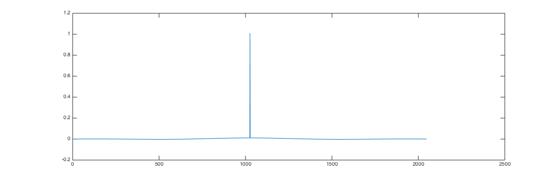
After sound testing the FIR filters I got so far, I thought that they sound much too filter-ish in that they greatly reduce both high (>1500Hz) and low (<200Hz) frequency components much more strongly than I would have wished. A FIR filter that just passes the signal through unmodified (with or without delay) is always just a single peak, so I decided to multiply the peak values for both ears by 5 to “multiply in” a dirac impulse. Before:

After:

4. Off-ear delay
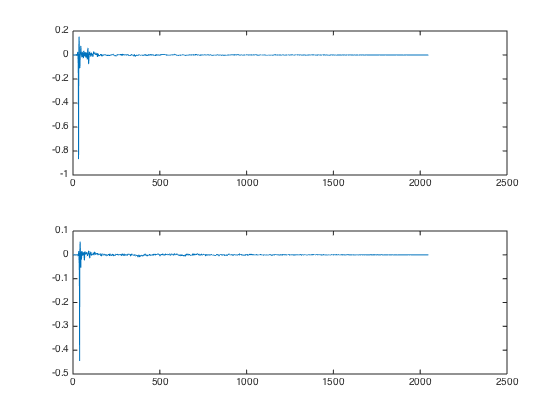
While the filters from #3 already sound pretty good, the spatial localization is still very bad. This is probably because so far, the signal is reaching both ears simultaneously. As calculated above, a 6 sample delay on the off-ear is required. Here’s a picture of the FIR coefficients with off-ear delay:
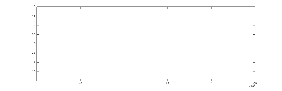
5. Inverse-FFT Equalizer for bass boost
As described above, one can use an array of complex values with phase 0 and various magnitudes to design FIR coefficients for a custom equalizer. I decided to fill my array with ones everywhere and then set the bins for frequencies less than 100 Hz to 5 and use a smooth 32-sample hanning falloff to blend between the two. That resulted in the following FIR coefficients:
Now I combined my FIR coefficients for both ears (step 1-4) with the bass boost equalizer by convolving the impulse responses, which yields the following FIR coefficients:

To verify that the FIR filters behave as intended, I performed a STFT analysis. These images show the delay time from left to right and the frequency from bottom (22.05kHz) to top (0Hz). The brightness of each point is the gain that is applied to the associated frequency band after the given delay. Here you can see that the signal that reaches the ear on the speaker side has a strong direct sound for all frequency bands with exponential falloff and a slightly slower falloff for low frequencies (top of image):

And on the next image you can see that the signal on the off-ear is much stronger filtered (as it should be) and therefore mostly limited to lower frequencies. Also, the signal is spread out over a longer duration, just like one would expect from a signal that includes many reflections.

BTW those FIR filters are precisely what is being used to simulate the L channel if you choose “Hajo’s echo-free 5.1 club sound system” as the sound engine in my headphone enhancer app. If you select “Hajo’s echo-free 5.1 system without bass boost”, I’m using the FIR coefficients from step 4.
Blocked FFT convolution
So now that we have a FIR filter for every channel-ear-combination that encodes all the delay, volume, frequency envelope and reflection effects that we’d apply for our surround sound simulation, it’s time to efficiently apply the FIR filter to our input signal.
Sound cards as well as the OS X audio system work with buffers, which means there is a fixed size of the chunks that we are receiving the audio signal in. We now:
- fft-transform that audio chunk
- multiply the result with the fft-transformation-result of our FIR filter coefficients
- apply the inverse fft transformation to the audio chunk
BTW, this approach is called blocked FFT convolution. You can buy a nice optimized FFT-implementation from Intel as part of the Composer XE compiler suite. Blocked convolution assumes that both your audio signal and your FIR filter coefficients are circular buffers, which is not the case for the filters involved in headphone surround simulation. So you’ll need to slightly modify the algorithm, which is then called overlap-save:
- zero-pad the FIR filter coefficients to twice the block length
- FFT-transform the padded FIR coefficients
- when new audio data arrives, keep the last audio chunk around in a history buffer
- FFT-transform the audio in the history buffer and in the current chunk to get an FFT result of twice the size as a single chunk
- multiply the result from #2 with the result from #4
- apply the inverse FFT transform. You will get an audio signal of twice the chunk size, because the FFT data was twice the chunk size long.
- only use the second half of the result from #6, because the first half contains the artifacts caused by non-circular FIR coefficients.
Final words …
Thank you for your attention. You now know the techincal, acoustical and mathematical approaches required to create your own surround sound simulation app for OS X. Of course, it’ll require you a bit of trial and error to guess volume, delay, frequency and reflection settings that “sound natural”, just like the FIR filters shown above weren’t exactly my first try ;)
If you liked this article, please support my work by buying my headphone enhancer product for “10 insert currency unit here” and thereby save all those silence-loving citizens of “insert subject hometown here” the headaches caused by loud music ;) Yes, I like Portal 2 :)
Old OS X – I stopped supporting Catalina: http://www.hajoheadphone.com/buy.html Windows: https://spatialsoundcard.com/